Project 2: A RV32I Toy CPU
IMPORTANT INFO - PLEASE READ
The projects are part of CS110P course project worth 2 credit points. As such they run in parallel to the actual course. So be aware that the due date for project and homework might be very close to each other! Start early and do not procrastinate.
Introduction
In this individual project, you will embark on a journey to create a toy RV32I CPU. Before diving into the task, please pay close attention to the following important points:
Any behavior that violates course rules is strictly prohibited. This includes viewing, copying or plagiarizing other individuals' circuits or codes. Violators will face severe consequences
You are allowed to use any built-in blocks of Logisim, except for the TTL, TCL, BFH mega functions and System On a Chip group, throughout this project.
Save frequently and commit frequently! Try to save your code in Logisim every 5 minutes or so, and commit every time you produce a new feature, even if it is small.
Don't move around the given inputs and outputs in your circuit, this could lead to loss of points.
Project 2.1: Implement a Single-cycle CPU (DDL: May 5th)
The Instruction Set
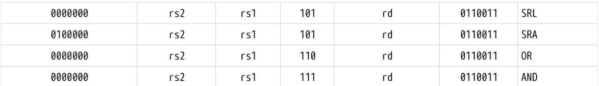
The instructions you need to implement are shown in the table below:
| Format | Instructions | Implementation |
|---|---|---|
| R | add | x[rd] = x[rs1] + x[rs2] |
| R | sra | x[rd] = x[rs1] >>s x[rs2] |
| R | slt | x[rd] = x[rs1] <s x[rs2] |
| I | srli | x[rd] = x[rs1] >>u shamt |
| I | sltiu | x[rd] = x[rs1] <u sext(immediate) |
| I | andi | x[rd] = x[rs1] & sext(immediate) |
| I | addi | x[rd] = x[rs1] + sext(immediate) |
| I | lw | x[rd] = sext(M[x[rs1] + sext(offset)][31:0]) |
| I | lh | x[rd] = sext(M[x[rs1] + sext(offset)][15:0]) |
| I | jalr | t =pc+4; pc=(x[rs1]+sext(offset))&~1; x[rd]=t |
| U | auipc | x[rd] = pc + sext(immediate[31:12] << 12) |
| U | lui | x[rd] = sext(immediate[31:12] << 12) |
| S | sw | M[x[rs1] + sext(offset)] = x[rs2][31:0] |
| S | sh | M[x[rs1] + sext(offset)] = x[rs2][15:0] |
| J | jal | x[rd] = pc+4; pc += sext(offset) |
| B | beq | if (x[rs1] == x[rs2]) pc += sext(offset) |
A detailed description of RV32I is provided in The RISC-V Instruction Set Manual Volume I: Unprivileged ISA (Version: 20240411). Some important information is also provided below. Please note that there are different versions of RV32I instructions, and referencing other documents or webpages may result in failing the test.
Instruction Formats
In the base RV32I ISA, there are four core instruction formats (R/I/S/U), as shown in the below figure. All are 32-bit long. The base ISA has IALIGN=32, meaning that instructions must be aligned on a four-byte boundary in memory.
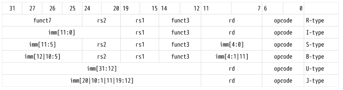
Here are details about RV32I Base Instruction Set (MSB to LSB), you can also find this table in The RISC-V Instruction Set Manual Volume I: Unprivileged ISA, page 554 (may proxy needed):

How to get start
We provided the template in Github Classroom to get started. Please clone your repo first. Opening proj_2_1_top.circ with logisim-evolution, you will find several subcircuits inside it.
TOPis the top-level circuit you need to complete. It represents the implementation of the target toy CPU that includes the subcircuits you designed. Please note that do not modify the packaging of the TOP circuit or any parts marked as "Don't touch", as failing to comply with this may result in failing the test cases.testbenchis a completed circuit provided by TAs for testing. You can write any binary format instruction to the instruction memory(ROM) and observe whether your circuit operates as expected. This circuit will not be used in grading, so feel free to make any attempts.
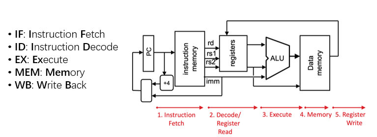
A single-cycle CPU through several stages,such as Instruction Fetch (IF), Instruction Decode (ID), Execute (EX), Memory Access (MEM), and Write Back (WB). And each stages may include multiple submodules. Here are some suggestions for your information:
- It's recommended that try to implement instructions one by one and you can start with LUI instructions! This method is debug-friendly.
- List all the signals you need, and try to classify them into different modules. Classifying signals helps complete circuits in the simplest way. You will find that the workload is much smaller in this way.
The instruction memory module in testbench, provided as a pre-configured ROM by TAs, stores the target instruction sequence for execution.
- The
testbenchcircuit already contains pre-wired interface signals between theTOPmodule andinstruction memory (ROM). You must properly drive these existing signals to achieve correct instruction retrieval. - No additional instruction memory component implementation is required in your
TOPdesign.
The TOP circuit incorporates predefined input/output ports for testing purposes, where most output signals chould be treated as ''probes''. These diagnostic signals may not interfere with your circuit implementation, but you are required to show the correct values throughout operation (Somtimes you maydon't care some of them). Detailed specifications for these signals can be found in the TOP I/O section.
TOP I/O
The inputs and outputs of top level are fixed in TOP circuit. It's not allowed to add extra pins in TOP circuit in your submission.
| Type | signal | bit width | description |
|---|---|---|---|
| input | clk | 1 | clock |
| input | rst | 1 | reset |
| input | inst | 32 | RV32I instruction from inst memory |
| output | inst_addr | 32 | current instruction address |
| output | mem_wen | 1 | memory write enable |
| output | mem_din | 32 | data written to memory |
| output | mem_dout | 32 | data from memory |
| output | mem_addr | 32 | address of memory |
| output | control_en | 1 | enable writing value to pc |
| output | control_pc | 32 | value written to pc |
| output | wb_en | 1 | regfile write enable |
| output | wb_addr | 5 | address written to regfile |
| output | wb_data | 32 | data written to regfile |
Restriction
In order to reduce your workload and help you pass the test smoothly, some restrictions are stipulated as follows. Please note these requirements take precedence over any conflicting descriptions in the Instruction Set Manual.
All data values must be represented in 2's complement format.
Implement byte-addressable data memory using
RAM(notROM) withasynchronous read. Each memory address corresponds to an 8-bit (1-byte) storage unit.For memory access operations:
- Only the lower 8 bits of
inst_addrare used to access the instruction memory (ROM). - Only the lower 16 bits of
mem_addrare used to access the data memory (RAM).
- Only the lower 8 bits of
Construct the register file using discrete
registercomponents.The CPU must initialize to a zero-state during power-on:
- All output pins in
TOPshall output zero values. - Register files and RAM contents must be cleared.
- Refer to the Power-on Reset (POR) in
Help > User's Guidefor implementation details.
- All output pins in
All instruction addresses (
inst_addr) are 2-byte aligned.Implement automatic misalignment correction:
- Example: Address
0x03(binary0b11) should be aligned to0x02(binary0b10) by truncating the least significant bit (LSB) to meet alignment requirements. - No explicit exception handling required beyond address correction.
- Example: Address
Test
For the convenience of calibrating each cycle, an additional counter has been added to the testbench, which you can ignore in your own design.
Local test
TAs provides a comprehensive local test script containing all instruction patterns, but the reference output does not explicitly mark don't-care signals. In Project 2.1, you must independently analyze and determine which signals can be safely disregarded during your implementation verification.
    chmod +x test.sh
    ./test.sh
This script is suitable for Linux systems. If you want to run it on other operating systems, you need to make some modifications.
Autograder test
The autograder will exclude validation of these don't-care portions through an internal filtering process. The testcase of Autograder is non-public, which means you need to consider all corners as much as possible. Please ensure that the local test passes when submitting a rating request to the Autograder. Notice: We will evaluate your final score based on which of your submissions is set as active.