IMPORTANT INFO - PLEASE READ
The projects are part of CS110P course project worth 2 credit points. As such they run in parallel to the actual course. So be aware that the due date for project and homework might be very close to each other! Start early and do not procrastinate.
Introduction
In this individual project, you will embark on a journey to create a toy RV32I CPU. Before diving into the task, please pay close attention to the following important points:
Any behavior that violates course rules is strictly prohibited. This includes viewing, copying or plagiarizing other individuals' circuits or codes. Violators will face severe consequences
You are allowed to use any built-in blocks of Logisim, except for the TTL, TCL, BFH mega functions and System On a Chip group, throughout this project.
Save frequently and commit frequently! Try to save your code in Logisim every 5 minutes or so, and commit every time you produce a new feature, even if it is small.
Don't move around the given inputs and outputs in your circuit, this could lead to loss of points.
Project 2.2: Implement a 5-Stage Pipelined Toy CPU (DDL: May 19th)
Project 2.1. Notice: A new template is provided for you to implement the instructions.
How to get start
We provided the template in Github Classroom to get started. Please clone your repo first. Opening proj_2_2_top.circ with logisim-evolution, you will find several subcircuits inside it.
TOPis the top-level circuit you need to complete. It represents the implementation of the target toy CPU that includes the subcircuits you designed. Please note that do not modify the packaging of the TOP circuit or any parts marked as "Don't touch", as failing to comply with this may result in failing the test cases.testbenchis a completed circuit provided by TAs for testing. You can write any binary format instruction to the instruction memory(ROM) and observe whether your circuit operates as expected. This circuit will not be used in grading, so feel free to make any attempts.
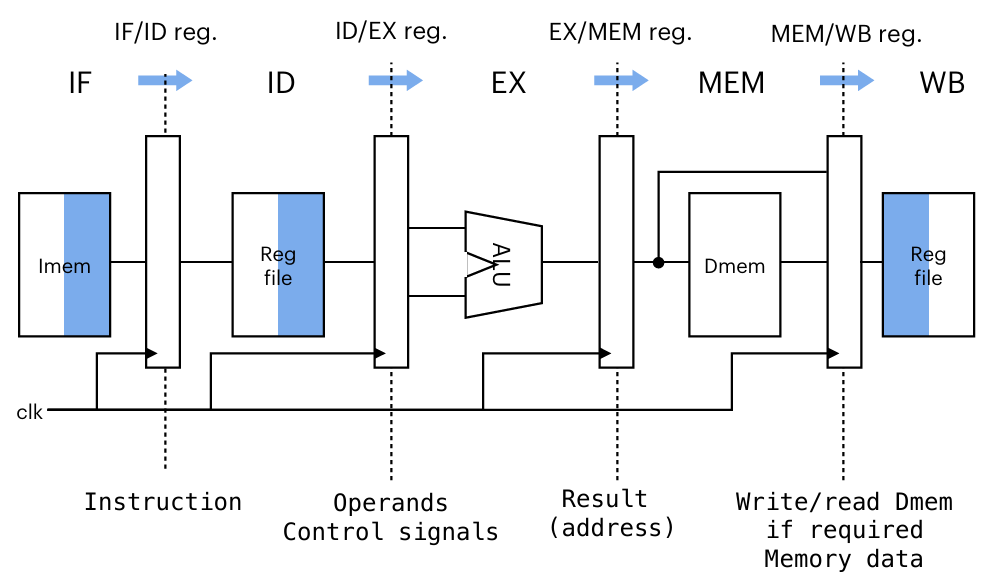
Recall the classic 5 stages of CPU executing an instruction: Instruction Fetch (IF), Instruction Decode (ID), Execute (EX), Memory (MEM), Write Back (WB). In a 5-stage pipelined CPU, multiple instructions are processed simultaneously at different stages. You need to be careful to handle the hazards in the pipeline. The explanation and requirements of the hazards are detailed in the Hazards.
You are recommended to implement in the following order:
- A single pipeline not solving any hazard
- Solving structural hazards
- Solving control hazards
- Solving data hazards
Hazards
Structural Hazards
Structural hazards occur when multiple instructions simultaneously compete for the same physical hardware resource. In a 5-stage pipelined CPU, these conflicts primarily affect memory access and register file operations. You need to address the hardware limitation in the register file, where concurrent read and write operations from different pipeline stages can create access conflicts. For standardized testing purposes, we assume that register file and data memory write at the falling edge of the clock signal, while the other registers and memory write at the rising edge.
Data hazards
Data hazards emerge when an instruction depends on data produced by a previous instruction which is still in the pipeline and not updated in the register file. These dependencies should be efficiently resolved through data forwarding. It routes computed values directly from the pipeline register to an earlier stage of the pipeline where they are needed.
However, data forwarding cannot completely resolve the case of a load delay slot as shown in the below example with x1. You can ignore this kind of data hazards because we have inserted one bubble or other instructions between the two instructions in the testcases.
  lw x1, 0(x3)
  add x7, x1, x0
Control hazards
Control hazards occur when the processor cannot determine which instruction to fetch next until the branch or jump result is obtained. You are required to implement the static branch prediction as follow.
- Initially assume that all branches or jumps are not taken and continue executing subsequent instructions, despite the branch condition is met or it is an unconditional jump instruction.
- When a branch or jump should be taken, flush the pipeline registers except for those storing the instructions fetched before the branch/jump instruction.
For standardized testing purposes, we assume that branch/jump resolution occurs in the EX stage, but the branch/jump taken signal (i.e. control_pc_mem in the TOP I/O) is fetched from the MEM stage for final determination.
TOP I/O
The TOP circuit incorporates predefined input/output ports for testing purposes, where most output signals chould be treated as ''probes''. These diagnostic signals may not interfere with your circuit implementation, but you are required to show the correct values throughout operation (Somtimes you may don't care some of them).
The inputs and outputs of top level are fixed in TOP circuit. It's not allowed to add extra pins in TOP circuit in your submission. The naming scheme of the output is {signal}_{stage}, which means the {signal} from {stage}.
| Type | signal | bit width | description |
|---|---|---|---|
| input | clk | 1 | clock |
| input | rst | 1 | reset |
| input | inst | 32 | RV32I instruction from inst memory |
| output | current_pc_if | 32 | current instruction address from IF stage |
| output | mem_wen_mem | 1 | memory write enable from MEM stage |
| output | mem_din_mem | 32 | data written to memory from MEM stage |
| output | mem_dout_mem | 32 | data from memory from MEM stage |
| output | mem_addr_mem | 32 | address of memory from MEM stage |
| output | control_en_mem | 1 | enable writing value to pc from MEM stage |
| output | control_pc_mem | 32 | value written to pc from MEM stage |
| output | wb_en_wb | 1 | regfile write enable from WB stage |
| output | wb_addr_wb | 5 | address written to regfile from WB stage |
| output | wb_data_wb | 32 | data written to regfile from WB stage |
Test
For the convenience of calibrating each cycle, an additional counter has been added to the testbench, which you can ignore in your own design.
For the purpose of ensuring smooth testing, we have inserted NOP instructions (i.e. addi x0,x0,0) in the testcases. We don't care the outputs for NOP instruction, but you need to ensure they do not affect the output results of subsequent instructions.
Local test
TAs provide two local tests containing all instruction patterns, but the reference output does not explicitly mark don't-care signals. localtest_0 has no data and control hazards, while localtest_1 includes some hazard cases. In Project 2.2, you must independently analyze and determine which signals can be safely disregarded during your implementation verification.
   chmod +x test.sh
  ./test.sh
This script is suitable for Linux systems. If you want to run it on other operating systems, you need to make some modifications. When your circuit is not complete, it is possible to encounter a timeout error.
Autograder test
The autograder will exclude validation of these don't-care portions through an internal filtering process. The testcases of Autograder include some testcases without data and control hazards, but you need to consider all corners as much as possible to get more scores. The testcases of Autograder are non-public. Please ensure that the local test passes when submitting a rating request to the Autograder. Notice: We will evaluate your final score based on which of your submissions is set as active.